There used to be a joke. Look up Engineering in the Yellow Pages – it says “See Boring”. A whole generation, or more accurately, the post modern generation, labelled engineering as being something for the un-adventurous, for those without passion or compassion. The subject has no style, taste or philosophy. It is an occupation not capable of generating thought or belief. Many years ago at a wedding breakfast, someone once said “I’m an engineer”, and we all thought “Oh, God, he’s going to be going on about roundabouts and concrete.”
Of course I am building up to something here. The documents I am looking at are challenges to my preconceptions. They are things of beauty, the elevations and plans for the Hammersmith Bridge. They were produced in the 1930s, around 40 years after the present bridge was built. The plans could possibly be assessing repairs, an evaluation, or survey. It actually says “alterations” on the designs, but such work was not carried out until the 1970s. The catalogue did not provide much information, as they don’t always go into detail. In this case, all it said was “drawings of Hammersmith Bridge.”
The plans and elevations breathe beauty.  They were hand drawn with ink on tracing paper. The artist, or technical draughtsman, produced vivid detail: a shadow, a bolt, a nut, cross-sections of wood. He would have been (and it would have been a he) a skilled craftsman, had completed a 7 year apprenticeship and practised the same trade for years. I imagine a team of draughtsmen in a drawing office, huge drawing boards and large windows allowing the natural daylight to flood in.
This stage was just one small element in the overall project. The drawing office would have had a brief about the requirements of the plans. An engineer would have put this together knowing the alterations needed. The draughtsmen probably worked from previous or even the original drawings.
The work is very factual, without freedom of expression. Of course it is. It had a technical purpose, with an absolute need for accuracy. Without accuracy the drawings would create further problems, expense and even the basic safety of the bridge.
But, within its sterility, the images are alive. You can see the structures and materials interacting with the forces. This is felt when looking at it face to face, in its entirety. The plans are large and to be viewed they need unrolling over a large table surface with weights holding the corers down. I can only provide snap-shots of detail opportunistically taken on my phone camera. The pictures do not convey the power of the plans.
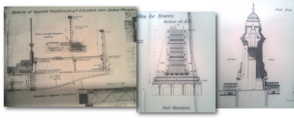
The text on the plans are technical terms and descriptions, but they also create poetry:
- Details of special cantilevers & C.I. Girders over Anchor Chamber
- End elevation
- Front elevation
- Section at A. A.
- ¼ ‘ web plate ½’ web cover
- Details of Abutments

- Chain tunnel
- Ordnance Datum
- 2 W I Bol
- Recess for Girder
- Centre Line of Chains
- Existing Chain Tunnel
- 2’ bolts into concrete
- Saddle
- River Bed
- London Clay
- Puddle
- Saddles for Towers
- Details of Gibs
- Special Cantilevers
- Existing Tunnels to be filled with concrete
I have to say, these plans and sections are more beautiful than the bridge is in real life. The bridge is covered in layers of paint that obscures the detail. Buses, traffic and pedestrians trundle over it. You cannot see the cross sections slicing through the structures, the bedrock and planks of wood. With the drawing, you are absorbed and intimate with the moment. It is just you and the plans. I would spend hours gazing at them, absorbing its many parts and the components. Unfortunately, I also have a job to do and I am certainly not paid to gaze at plans.
Were these plans ever used for repairs? I don’t know. They may have been plans to assess potential repairs that were never carried out. Maybe the war got in the way.
If they were drawn for actual repairs, were the plans ever used on site? It’s likely these plans were the copies not used on site and so the ones in better condition. Usually, the best condition copies were kept for the records, which turned into archives. Although, on some of the plans there are annotations, “not correct for location” and possibly amendments pencilled in on large joints.
Perhaps they were drafts. I like to think of them as working copies, being taken onsite, been well used and bashed around by the teams of engineers and construction workers. Those men whose job it was to locate the existing chain tunnel at section A.A., drill 2” bolts into concrete, centre the line of chains, fill the existing tunnels with concrete, and recess the girders. Workmen not with hard hats, high visibility jackets, or steel toe caps, but tough twill suits, study shoes, pipes and cigarettes. And shoved under their arms, tightly rolled up things of beauty.
References
The plans are found within the London Metropolitan Archives. Originally they were produced for London County Council in the Chief Engineer’s Department: Roads, Tunnels, Bridges and Ferries. The reference for the records of that department are found under LCC/CE/RB.


One thought on “Engineering is a thing of beauty.”